Table of Contents
Intro
In the following the Gross-Pitaevskii equation, $$ i\partial_t \psi = \frac{-\hbar}{2m}\nabla^2 \psi + \alpha |\psi|^2 + G\left(n_R + \frac{\eta P}{\Gamma}\right) + \frac{i(Rn_R - \gamma_{LP})}{2} $$ where $$\partial_t n_R = -(\Gamma + R|\psi|^2)nR + P$$ is solved with the following parameters: $\alpha$ = 0.0004 µm2 ps-1, $\gamma_{LP}$ = 0.2 ps-1, $\Gamma$ = 0.1 ps-1, $G$ = 0.002 µm2 ps-1
The system is driven with Gaussian pumps of the form $P(\vec{r}) = p\exp(-(\frac{\vec{r} - \vec{r}_0}{\sigma})^2)$. In the following graphs $\sigma$= 1.2 µm, corresponding to a FWHM of 2.826 µm, and p is tuned so that they are just over the threshold power density.
All the code is available on Github
The Penrose crystal
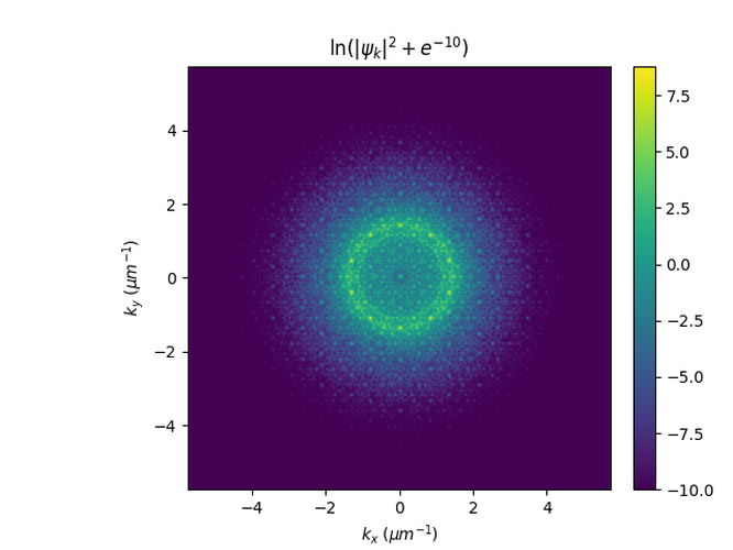
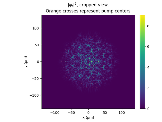
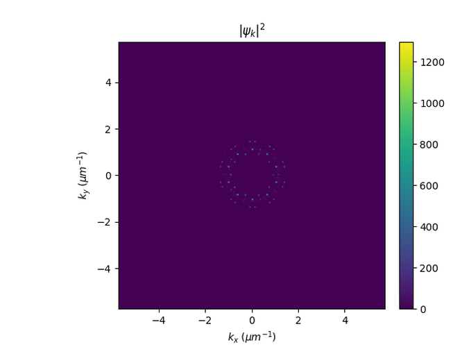
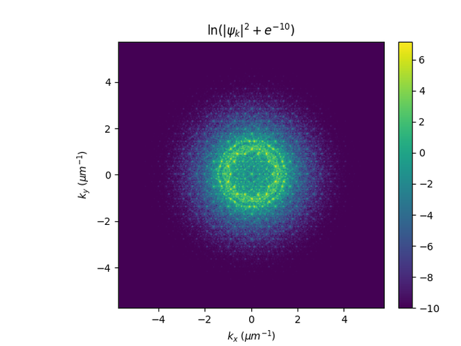
Here the pumps are placed at the vertices of a Penrose tiling with diameter d.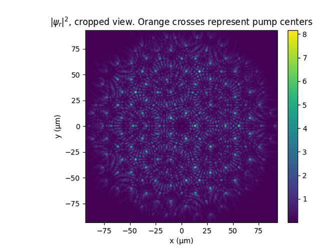
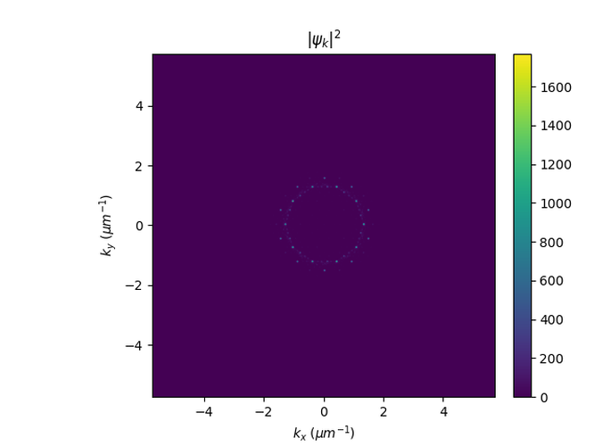
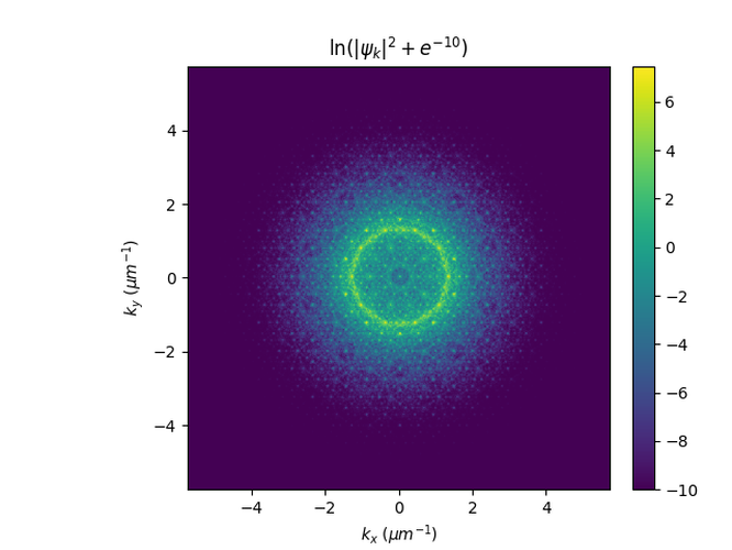
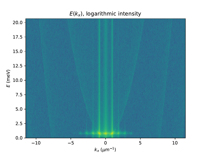
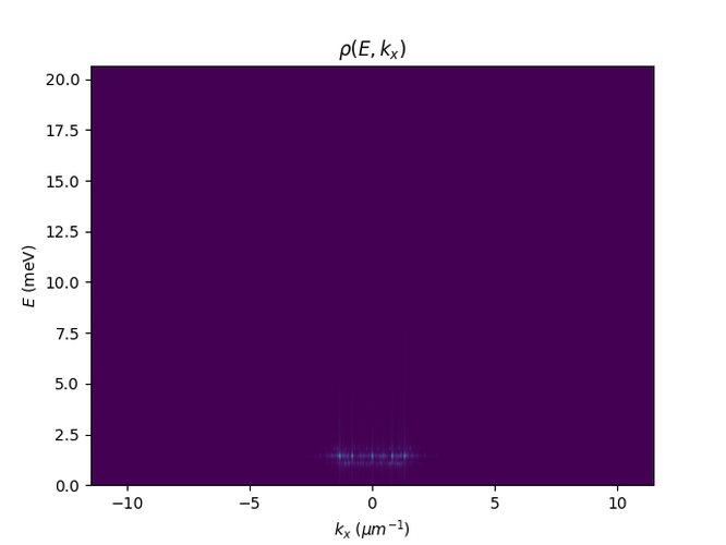
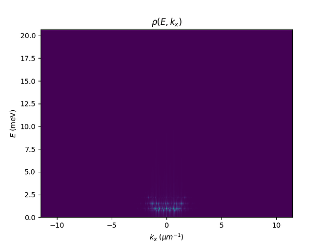
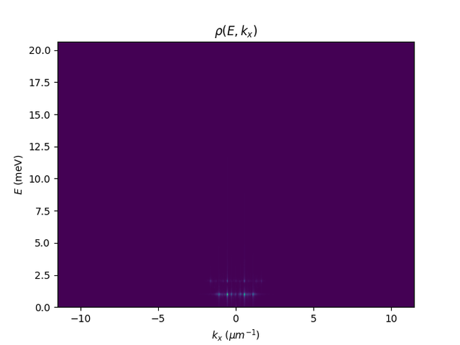
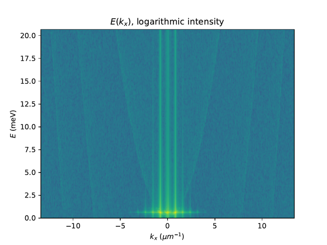
And then the dispersion relation: {{ graph(name="penrosedispersionr90d4p24n1024s1.2dt0.1.png", caption="Dispersion relation of E and kx, linear scale) }}
We can compare to simulations with smaller or larger tilings with the same number of pumps.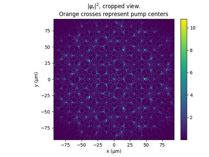
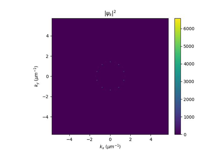
The Monotile Crystal
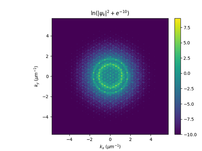
Here the pumps are placed at the vertices of a hat monotile tiling, using a method by Hastings Greer. A large tiling is generated and saved to a file. The tiliing is then cropped in the simulation so that a rectangular grid is obtained.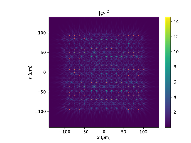
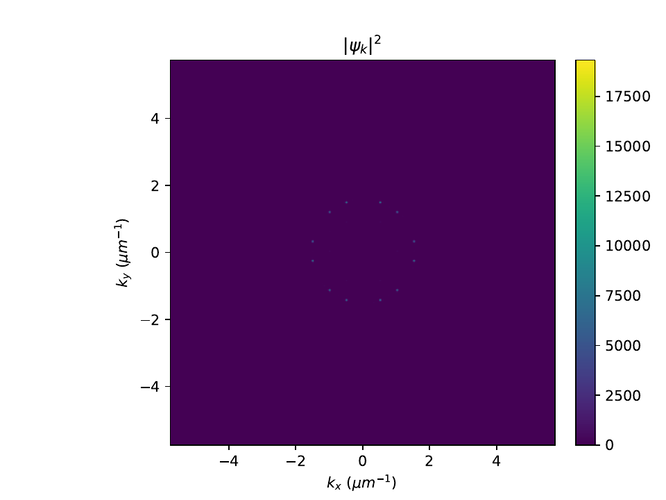
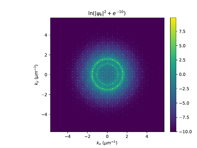
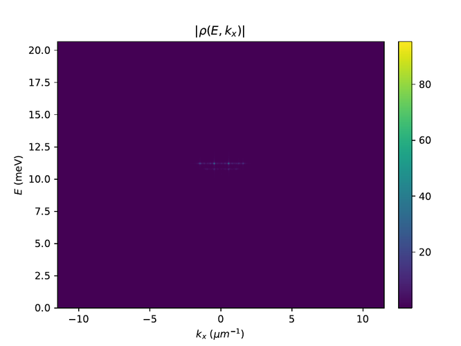
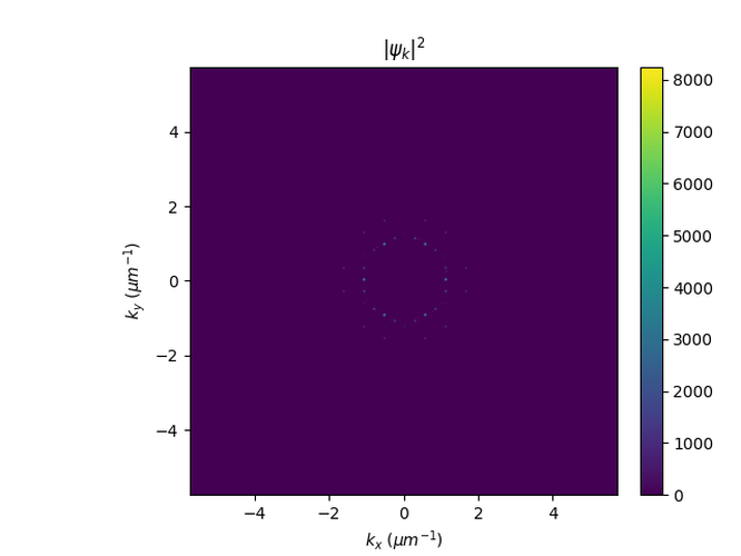
And to compare to a smaller grid in size: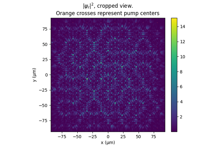
Sierpiński Triangles
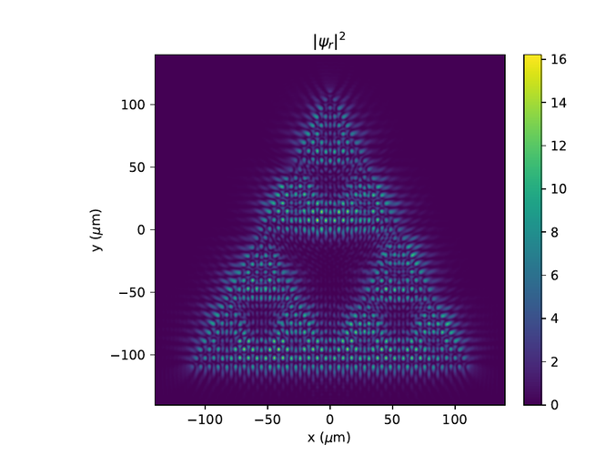
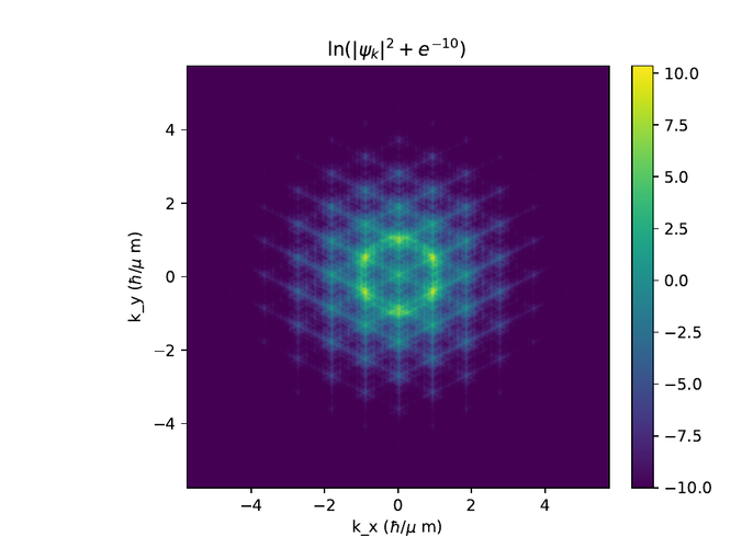
Here the pumps are arranged at the vertices of a Sierpiński triangle.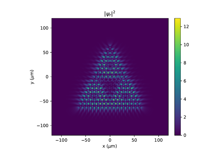
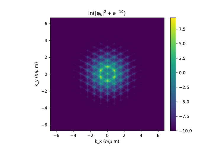
A larger triangle with more grid points.